Decoding Fine-Pitch Flex: The Reality of Sourcing FFC and FPC Connectors
An engineer's deep dive into the practical design trade-offs between FFC/FPC layout strategies, micro-pitches, and avoiding common board-to-board layout pitfalls.
We have all been there at 2:00 AM, staring at a high-density schematic wondering if we can actually squeeze another parallel bus onto a flexible printed circuit. When you are dealing with cramped enclosures, traditional rigid board-to-board interconnects or heavy backplane architectures just take up too much vertical real estate. That is where Flexible Flat Cables (FFC) and Flexible Printed Circuits (FPC) save the day. But choosing the right connector housing isn't just about picking a pitch out of a catalog and hoping for the best. If you don't account for trace impedance, cross-talk, and mechanical retention up front, you are setting yourself up for a nightmare during signal integrity testing.
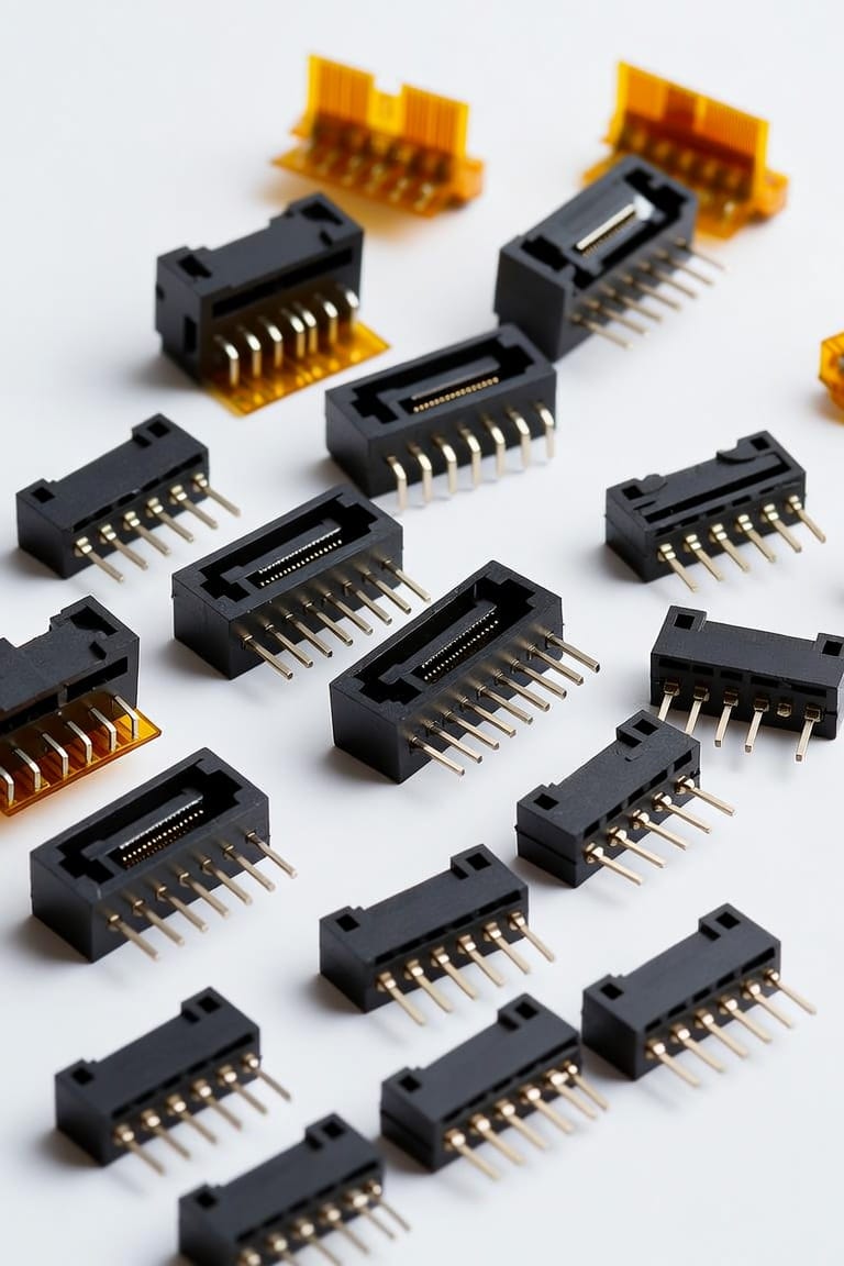
Let's look at what is happening on the bench with Amphenol Aorora's hardware line, specifically their 0.50mm pitch lineups like the F331 and F31L series. One detail that stands out from an assembly standpoint is their dual-beam contact architecture. If you've ever had to stock two entirely separate line items for top-contact and bottom-contact PCB layouts, you know how quickly that balloons your bill of materials (BOM). Dual-beam contacts bypass this entirely by gripping the exposed flex copper from both sides. This gives you a lot more freedom when routing traces across multi-layer designs, and it keeps production simple because the same connector works regardless of whether your cable feeds in face-up or face-down.
But a good contact interface is only half the battle. You also have to think about how that cable stays put when the device is dropped or subjected to industrial vibration. Amphenol Aorora uses a mix of back-flip and front-flip Zero Insertion Force (ZIF) actuators alongside integrated side-catcher locks. When you slide the cable in and flip the latch down, those physical side ears mechanically lock into notches on the cable jacket. It gives you a highly tactile click that lets the assembly team know it's seated perfectly, reducing the risk of a loose connection down the line.
On the high-speed side of things, select variations in this portfolio are engineered to match strict impedance profiles. When you're pushing high-frequency lines up to 25 Gbps for advanced display panels or camera feeds, any variations in geometry at the mating interface will cause impedance discontinuities. By keeping the contact path short and optimizing the layout inside the plastic housing, these connectors manage to maintain excellent signal integrity without requiring an oversized, bulky footprint.