Alignment Tolerances and Mating Mechanics for Multi-Board Assemblies
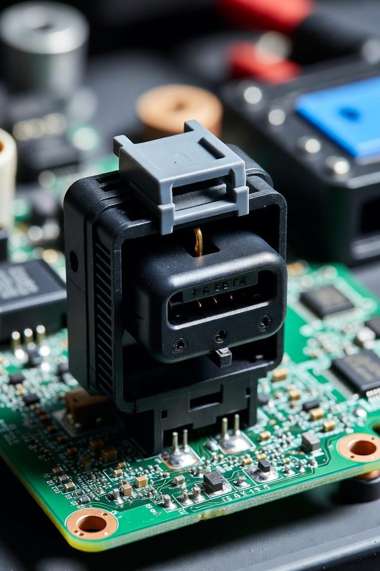
The Challenge of Multi-Connector Alignment
When an electronic product enclosure requires mating two large rigid circuit boards using multiple parallel board-to-board connectors, mechanical tolerance stack-up becomes a critical failure point.
Manufacturing variations in PCB hole drilling, connector placement during reflow, and enclosure mounting boss positions prevent perfect alignment across all connector pairs simultaneously.
Strategies for Reliable Multi-Board Alignment
- Use One Rigid Pair with Floating Secondary Connectors: Select one high-precision rigid connector pair to establish the primary alignment datum. Use floating board-to-board connectors for all secondary inter-board connections to absorb positional misalignment.
- Integrate Mechanical Guide Pins: Incorporate robust metallic or molded plastic guide posts on the main PCB or enclosure frame. Guide pins align the parallel circuit boards prior to connector contact engagement, preventing bent pins caused by off-center blind mating.
- Optimize SMT Pad Stencil Tolerances: Ensure surface-mount connector footprints utilize exact pad geometries recommended by manufacturers to avoid floating connectors out of position during solder reflow liquid surface tension alignment.